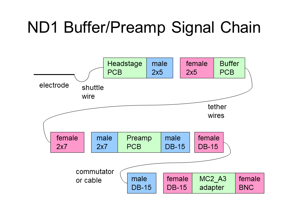
The path of an electrode signal from the electrode tip to the recording system passes through many components.
On the microdrive itself, a stiff electrode moves relative to the printed circuit board (PCB) within the microdrive.
A thin flexible wire connects these together, while permitting relative movement.
From another pad on the PCB, there may be a fixed reference electrode.
These signals pass through the microdrive connector, which also carries motor drive signals.
The microdrive connector mates to a tether connector on the free end of the tether.
Just beyond the tether connector, buffer electronics provide some current gain for each electrode signal.
The buffer isolates the high impedance electrode from the low impedance tether, reducing cross coupling effects within the tether.
At the supported end of the tether, a multi-channel preamplifier amplifies the difference between electrode signals into a voltage range suitable for analog to digital conversion.
The preamplifier also limits the bandwidth of the output signal.
The preamplifier may also be disabled by the motor blanking signal, reducing disturbance to the signal filter by large motor currents cross coupling to electrode signal paths.
RP Metrix provides basic components depicted in this diagram.
Many investigators make or buy other versions of these components to better suit their own requirements.